Basics
What is polarization? The direction of light vibration and its meaning in optical design
Polarization is a physical phenomenon in which the electric field of light — an electromagnetic wave — vibrates in a biased direction rather than uniformly. Many familiar optical devices are designed around controlling polarization, including the display principle of liquid crystal displays, the removal of reflected light by camera polarizing filters, and the stereoscopic effect of polarized 3D glasses. At the same time, when polarized light enters an anisotropic material, birefringence occurs, disturbing the polarization state that was supposed to be under control and causing problems such as image bleeding and interference fringes. This article organizes polarization from its physical definition through the classification into linear, circular, and elliptical polarization, the principles of polarizers and analyzers, practical use in optical devices, and its relationship with birefringence.
📌 Three-point summary
- Polarization is a state in which the direction of electric field vibration in light (an electromagnetic wave) is biased toward a specific direction; it is classified into linear, circular, and elliptical polarization according to the shape traced by the vibration
- Combining a polarizer with an analyzer lets transmitted light intensity be controlled by the angle θ according to Malus’s law, I = I₀cos²θ; this is the basis for how liquid crystal displays and PL filters work
- When polarized light passes through an optical component with birefringence, a phase difference arises and the polarization state becomes disturbed. A low-birefringence design governs image quality in optical systems that rely on polarization
What is polarization? A physical definition based on the direction light vibrates in
Light is an electromagnetic wave that propagates while its electric field (and magnetic field) vibrates within a plane perpendicular to the direction of travel. Because light from a natural source is emitted randomly by countless atoms and molecules, the direction of electric field vibration is not biased toward any particular direction and is distributed with equal probability in every direction. This state is called unpolarized light (natural light). Light whose electric field vibration is instead biased toward a specific direction is called polarized light (optics-words, what is polarization).
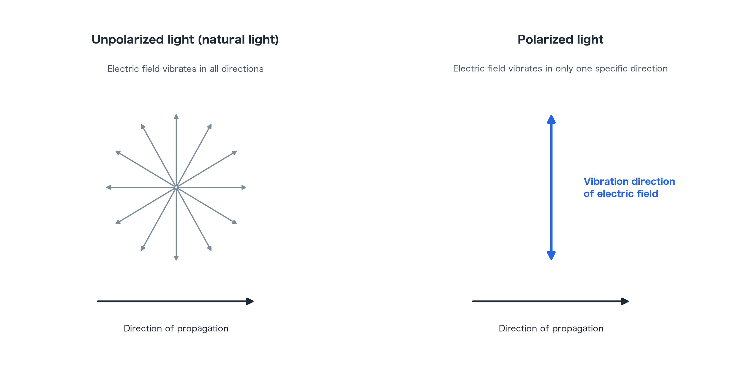
Taking the direction of travel as the z-axis, the x- and y-components of the electric field can be written as Ex = Ex₀cos(kz − ωt) and Ey = Ey₀cos(kz − ωt + δ), where δ is the phase difference between the two components. The combination of this phase difference δ and the amplitude ratio Ex₀/Ey₀ determines the trajectory traced by the tip of the electric field vector — that is, the polarization state (techno-synergy, what is polarization).
Types of polarization Linear, circular, and elliptical polarization
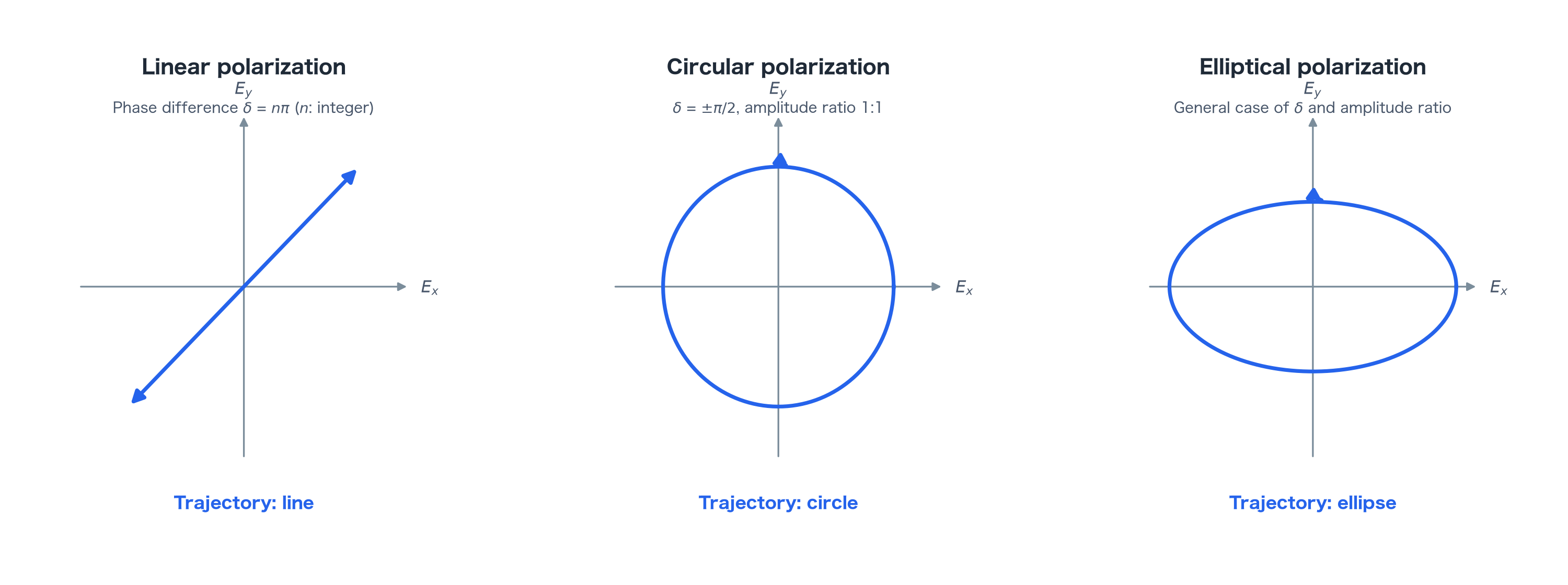
Polarization is classified into three types according to the shape traced by the tip of the electric field vector.
When the phase difference δ is 0 or an integer multiple of π, the x- and y-components vibrate either in phase or in antiphase, and the electric field vector oscillates back and forth along a single straight line. This is linear polarization. The tilt angle θ of the vibration plane is given by tanθ = Ey₀/Ex₀.
When the phase difference is δ = ±π/2 + 2mπ (m an integer) and the amplitudes are equal, Ex₀ = Ey₀, the tip of the electric field vector traces a circle when viewed along the direction of travel. This is circular polarization, distinguished by its direction of rotation into right-handed and left-handed circular polarization.
Both of these are special cases; under the general condition of an arbitrary phase difference and amplitude ratio, the tip of the electric field vector traces an ellipse. This is elliptical polarization, of which linear and circular polarization are included as special forms (katsura-opto, circular polarization and linear polarization; optics-words, what is polarization). Quarter-wave plates and half-wave plates are optical elements that use a birefringent material to artificially introduce a phase difference between two polarization components, converting linear polarization into circular polarization, or into linear polarization with a rotated vibration plane (fiberlabs, the principle of wave plates).
The principles of polarizers and analyzers, and Malus’s law
An optical element that extracts only linear polarization in a specific direction from unpolarized light or light in an arbitrary polarization state is called a polarizer. The same type of element is called an analyzer when it is used to determine the vibration direction of transmitted linear polarization (ipros, the polarization of light).
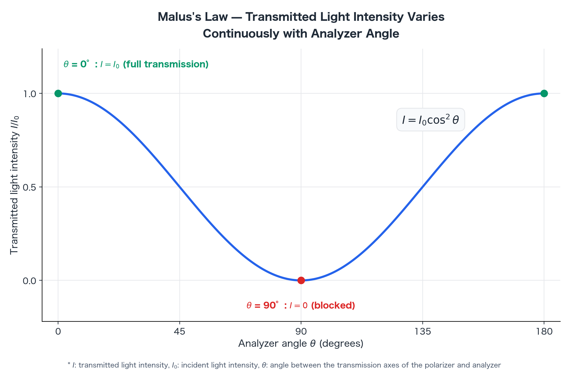
When linear polarization that has passed through a polarizer enters an analyzer whose transmission axis is tilted by an angle θ, the transmitted light intensity I relative to the incident light intensity I₀ is given by
I = I₀cos²θ
. This is Malus’s law (3B Scientific Japan, Malus’s law). At θ = 0° (transmission axes parallel), I = I₀ and the light passes through unchanged; at θ = 90° (transmission axes crossed), I = 0 and the light is blocked. Both the brightness control in liquid crystal displays and the adjustment of a PL filter’s effect make use of this angular dependence.
How polarization is used in everyday optical devices
Liquid crystal displays
A liquid crystal panel is basically a liquid crystal layer sandwiched between two polarizing plates with their transmission axes crossed. With no voltage applied, the twisted liquid crystal molecules rotate the plane of polarization by 90°, so light passes through the polarizing plate on the opposite side; with voltage applied, the liquid crystal molecules align, the rotation of the polarization plane disappears, and light is blocked. Switching between transmission and blocking in this way controls the brightness of each pixel (Sharp, the principle of liquid crystal displays; Tokyo University of Science, Furue Laboratory, TN cells and polarization).
Camera polarizing filters (PL filters)
Light reflected from a water surface or a glass surface becomes more strongly polarized as the angle of incidence approaches the Brewster angle (optics-words, the Brewster angle). A PL filter is built so that the transmission axis of its internal polarizing film can be rotated; by orienting this axis perpendicular to the vibration direction of the reflected light, it selectively attenuates the reflected component, making it possible to capture underwater subjects or the color of the sky more clearly (Canon, PL filters).
Polarized 3D glasses
Polarized 3D video is a technology that projects the images for the left and right eyes in different polarization states and separates them using glasses fitted with corresponding polarizing filters. The current mainstream approach uses circular polarization, assigning right-handed circular polarization to one eye and left-handed to the other. Because the direction of rotation of circular polarization does not change even when the head is tilted, it offers greater freedom of viewing posture than the linear polarization approach (AV Watch, stereoscopic 3D viewing using polarization).
Relationship with birefringence A factor that disturbs the polarization state
When linearly polarized light passes through a material whose refractive index is anisotropic (a birefringent material), a phase difference (retardation) R = Δn × d arises between the ordinary and extraordinary rays. This phase difference generally changes the transmitted light into elliptical polarization. The polarization state changes continuously with the magnitude of the phase difference: a phase difference of exactly a quarter wavelength brings the light close to circular polarization, while a half wavelength produces linear polarization with a rotated vibration plane. In other words, birefringence acts as a factor that unintentionally disturbs the polarization state in parts of a system that were not deliberately designed as wave plates.
Crossed-Nicols observation under a polarizing microscope is a measurement technique that turns this property to its advantage. When a polarizer and analyzer (Nicol prisms) are arranged with their transmission axes crossed, a colorless, transparent sample with no birefringence blocks all the light. However, when a birefringent sample is inserted, the polarization state of the transmitted light is disturbed, allowing part of it to pass through the analyzer, which is observed as interference colors (J-STAGE, the principle and structure of the polarizing microscope). This is why polarizing microscopes are used to evaluate birefringence in optical components.
Birefringence in optical resin becomes a problem specifically in optical systems that rely on controlling polarization, such as liquid crystal displays, HUDs, and AR glasses. The physical principle of birefringence, the mechanisms behind orientation birefringence and stress birefringence, comparisons across resins, and countermeasures during molding are detailed in the birefringence article (What is birefringence | iupizeta.mgc.co.jp). Note that the disturbance of polarization caused by birefringence does not show up in transparency indicators such as total luminous transmittance or haze. The differences among these indicators are explained in a separate article (The difference between total luminous transmittance and haze | iupizeta.mgc.co.jp).
Where Iupizeta EP fits Suitability for polarization-related optical systems through low birefringence
Mitsubishi Gas Chemical’s optical resin Iupizeta EP is an optical resin whose proprietary molecular design minimizes birefringence (Iupizeta EP product information). As noted earlier, birefringence is a factor that disturbs the polarization state, so low birefringence is an advantageous property for preserving image quality in optical systems that rely on polarization control. The mechanism behind it and comparisons across resins are covered in the birefringence article (What is birefringence).
Iupizeta EP is offered in grades spanning a refractive index (nd) of 1.616–1.671 and an Abbe number (νd) of 19.2–25.8, with intended applications including smartphone camera lenses, automotive cameras, and precision lenses for various optical devices (Iupizeta EP product information). Given the trade-off whereby raising refractive index tends to increase birefringence, a design that maintains low birefringence is worth considering when selecting materials for precision optical systems that rely on polarization.
Summary
Polarization is a state in which the direction of electric field vibration in light is biased toward a specific direction, and it is classified into linear, circular, and elliptical polarization. Combining a polarizer with an analyzer controls light intensity according to Malus’s law, underpinning the operating principle of familiar optical devices such as liquid crystal displays, PL filters, and polarized 3D glasses. At the same time, when polarized light passes through a birefringent material, a phase difference arises and the polarization state becomes disturbed. In material selection for optical systems that rely on polarization, suppressing birefringence is a key design factor governing image quality.
About Iupizeta EP
Iupizeta EP is an optical resin developed by Mitsubishi Gas Chemical, offered in grades spanning a refractive index of 1.616–1.671 and an Abbe number of 19.2–25.8, and it is also notable for its low birefringence achieved through proprietary molecular design. For detailed property data or to discuss sample provision, please feel free to reach out through the inquiry form on the official website.
Some images and text in this article were created with the help of generative AI.


Recommended articles