Basics
What are MT ferrules and MPO connectors? Higher fiber counts and differences in standards
📌 Three-point summary
- An MT ferrule is a resin-molded rectangular part that arranges and holds multiple optical fibers, and it is the core component of the MPO connector.
- The structure and dimensions of MPO connectors are specified in JIS C 5982, which covers 2–12 fibers in one row and 16–24 fibers in two rows. A separate standard covers 16-fiber versions.
- Single-mode versions require accuracy that keeps core axial misalignment below 1 μm, so the molding accuracy and dimensional stability of the ferrule affect connection loss.
Relationship between MT ferrules and MPO connectors
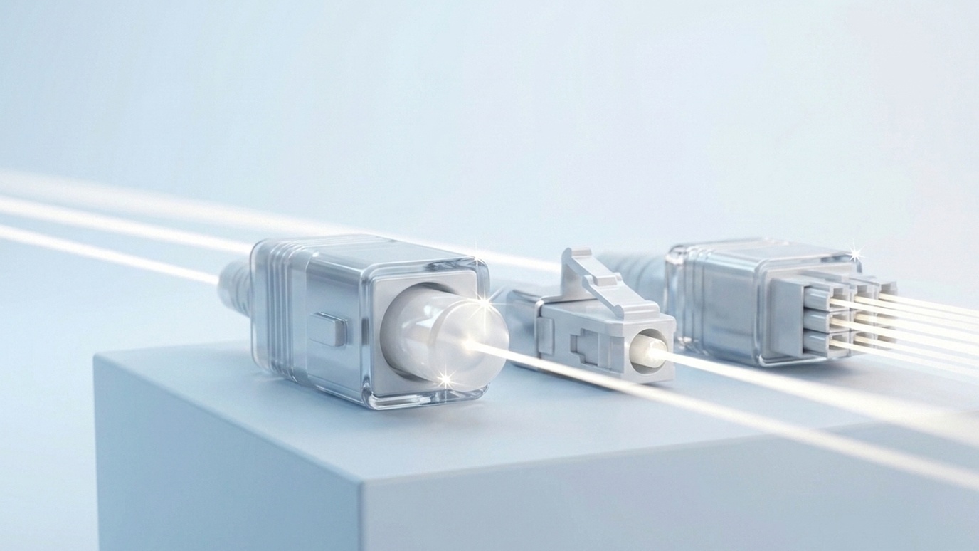
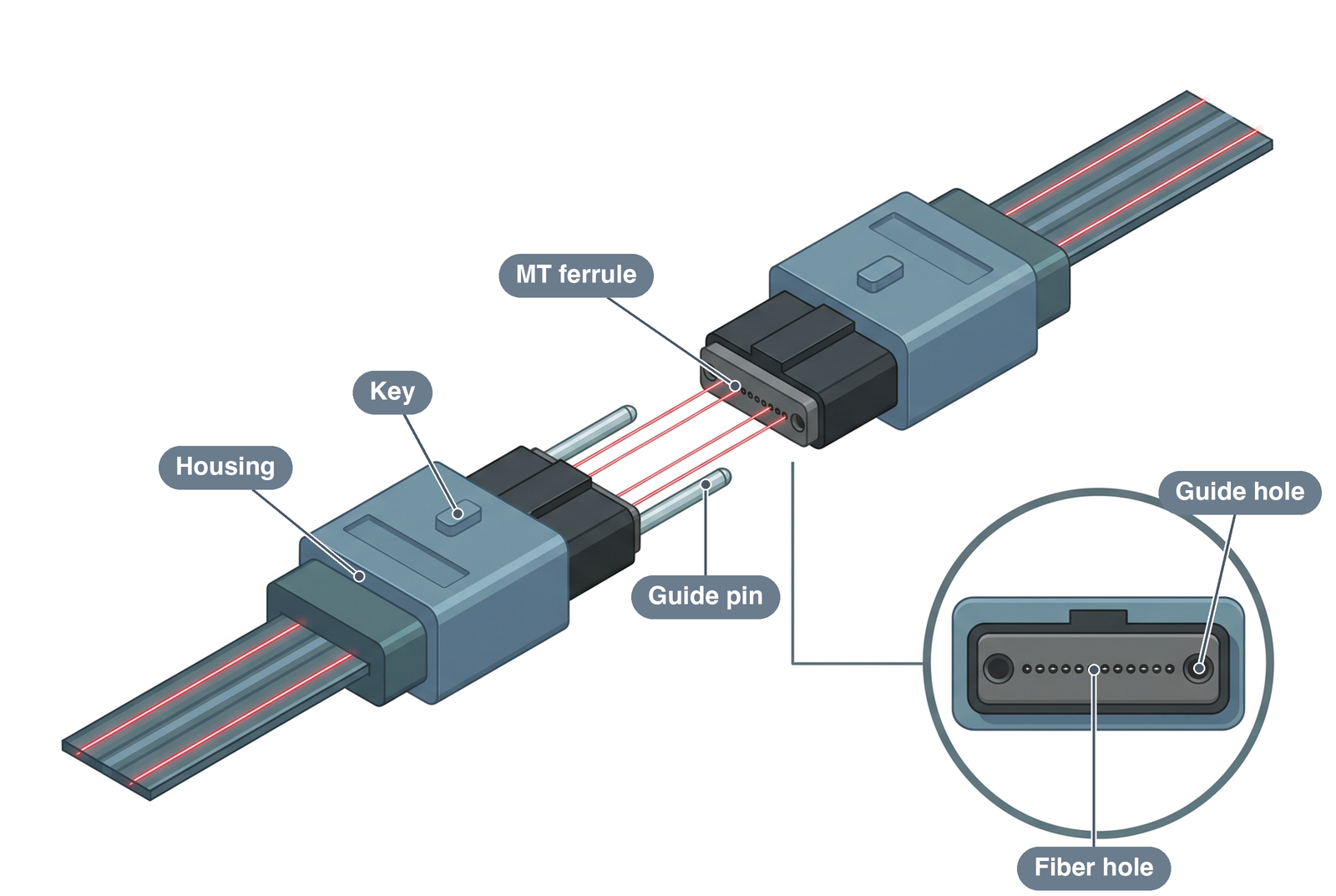
An MPO connector is a multi-fiber optical connector in which an MT ferrule is housed in a housing so that it can be connected simply by pushing it in. Because one connector can connect multiple optical fibers at once, it is used in applications such as parallel optical transmission in data centers.
Structure of the MT ferrule
An MT ferrule (mechanically transferable ferrule) is a rectangular part that arranges and holds multiple optical fibers with high positional accuracy. A ferrule is a part that holds the end of an optical fiber and sets its position.
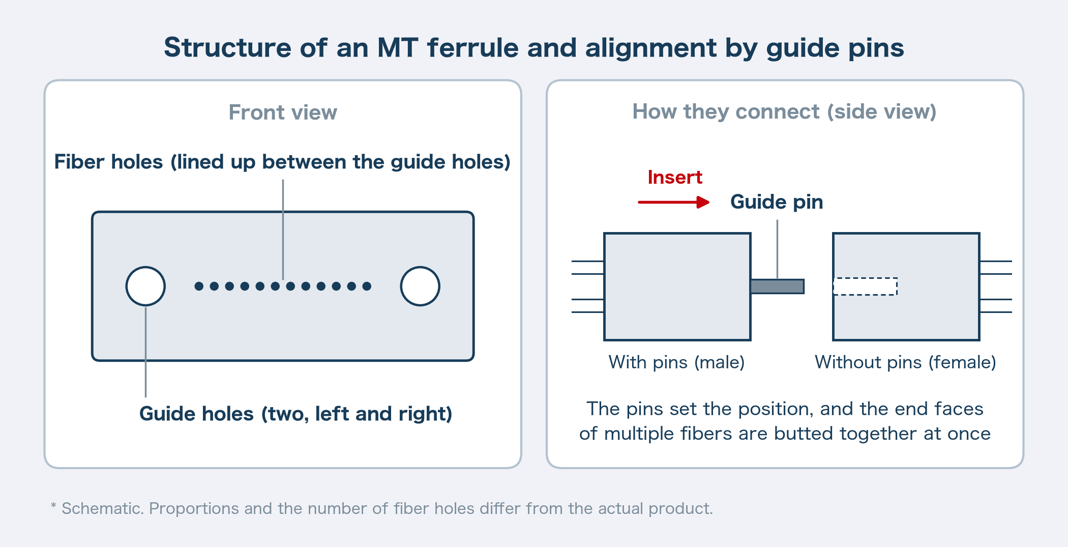
Under the standards, the ferrule for MPO connectors is usually a rectangle with outer dimensions of 6.4 mm × 2.5 mm. It has two guide holes on the left and right, and guide pins 0.7 mm in diameter are passed through them to align it with its counterpart. The holes for optical fibers are arranged between these two guide holes.
When connecting, guide pins fixed in one ferrule are inserted into the guide holes of the other ferrule. Because the pins set the position, the end faces of multiple fibers can be butted together at the same time.
| Item | Details |
|---|---|
| Ferrule outer dimensions | Usually a 6.4 mm × 2.5 mm rectangle |
| Guide pin diameter | 0.7 mm |
| Fiber hole pitch | 0.25 mm within a row; 0.5 mm between rows for two-row versions |
| Fiber count, one-row versions | 2–12 fibers |
| Fiber count, two-row versions | 16–24 fibers |
Structure of the MPO connector
The MPO (multi-fiber push-on) connector is a connector in which an MT ferrule is housed in a housing. It uses a push-pull mechanism: it connects when pushed in and disconnects when pulled. The ferrule is pushed in the optical axis direction by a spring inside the housing, and the fiber end faces come into contact when connected. The housing has one key, which sets the orientation relative to the counterpart.
To connect two connectors, an adapter that holds them facing each other is used.
Pinned and unpinned versions: male and female
Some MPO connectors have guide pins fixed in the ferrule, and others have no pins. Those with pins are called male, and those without are called female. The standard shows a configuration in which an unpinned female connector, a pinned male connector, and an adapter are combined for connection.
Standards for MT ferrules and MPO connectors
JIS and IEC standards
MT connectors and MPO connectors have separate standards in the Japanese Industrial Standards (JIS). The MT connector is called type F12, and the MPO connector type F13. An interface standard specifies the dimensions of the connecting section so that connectors can be connected to each other.
| Standard | Scope |
|---|---|
| JIS C 5981 | Type F12 multi-fiber optical fiber connector (MT connector) |
| JIS C 5982 | Type F13 multi-fiber optical fiber connector (MPO connector) |
| JIS C 5964-5 | Interface standard for MT connectors (type F12) |
| JIS C 5964-7-1, 5964-7-2 | Interface standard for MPO connectors (type F13), one row and two rows |
| IEC 61754-5 | Interface dimensions for the MT connector family |
| IEC 61754-7-1, 61754-7-2 | Interface dimensions for the MPO connector family, one row and two rows |
| TIA-604-18 | 16-fiber MPO-type connector |
JIS C 5982 corresponded to IEC 61754-7 until its 2001 revision. Because IEC 61754-7 was revised from a product standard into a standard that specifies only the interface, there is currently no corresponding international standard. In the IEC, the MPO connector family is divided into 61754-7-1, which covers one-row versions, and 61754-7-2, which covers two-row versions.
Differences between MPO and MTP
MPO is the name of a connector type defined by the standards, while MTP is a product name trademarked by a specific manufacturer. MTP conforms to the MPO standards and can be connected to MPO connectors. MTP includes improvements beyond the scope of the MPO standards, such as elliptical guide pin tips, a ferrule that can move inside the housing, and a removable housing. Both use MT ferrules.
Trend toward higher fiber counts
The fiber count of MPO connectors has increased along with the rising communication speeds of data centers.
| Arrangement | Fiber count | Main standards | Example applications |
|---|---|---|---|
| One row | 2–12 fibers | IEC 61754-7-1, JIS C 5964-7-1 | 40GbE (12-fiber version) |
| Two rows | 16–24 fibers | IEC 61754-7-2, JIS C 5964-7-2 | 100GbE (24-fiber version) |
| One or two rows | 16 fibers per row | TIA-604-18 | 400GbE |
12-fiber and 24-fiber versions
The one-row 12-fiber version uses four fibers for transmission and four for reception in 40GbE. The two-row 24-fiber version supports a configuration that uses ten fibers each for transmission and reception in 100GbE. For standardized 40GbE and 100GbE, the use of 12-fiber and 24-fiber versions is recommended.
16-fiber version
In 400GbE, connectors with 16 fibers in a single row, eight for transmission and eight for reception, are also used. The 16-fiber version arranges 16 fibers in a ferrule with the same outer shape as the 12-fiber version. The diameter and position of the guide pins and the position of the key differ from those of the 12-fiber version, so it cannot be mistakenly connected to a 12-fiber version. TIA-604-18 is a standard that specifies 16 fibers in one or two rows.
Ferrules with 48 or more fibers
Ferrule fiber counts are trending upward, from 12 to 24 and then to 48, or from 16 to 32. As products, there are ferrules with up to 72 fiber holes. As the fiber count increases, every hole must meet the positional accuracy, so the effect on yield compounds as a power of the number of holes.
Accuracy and materials required of MT ferrules
Connection loss and dimensional accuracy
When optical fibers are connected, misalignment of the core positions causes light to leak and connection loss to increase. The core diameter of a single-mode optical fiber is about 8–10 μm, located at the center of a fiber 125 μm in diameter.
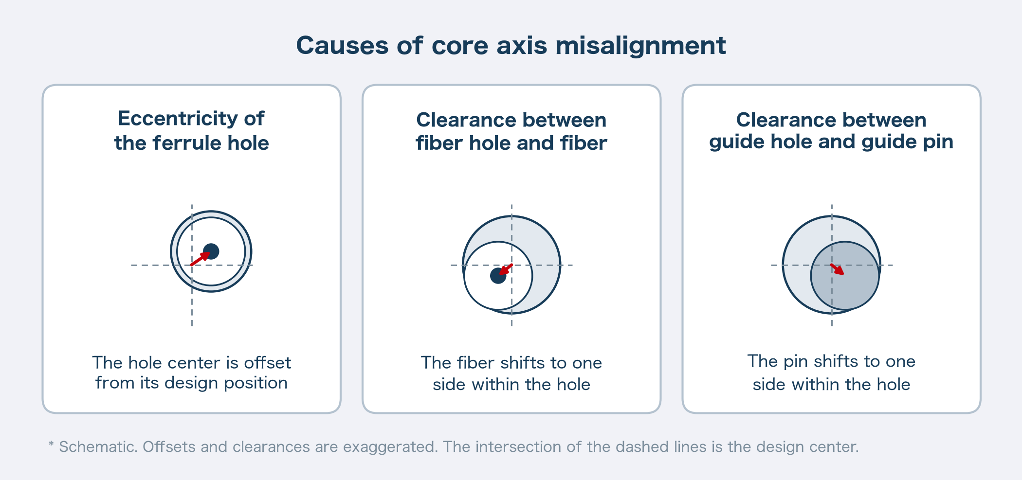
To keep connection loss at 0.5 dB or less, the axial misalignment between the cores of two fibers must theoretically be 1.6 μm or less. The axial misalignment allowed for one connector is half of that, 0.8 μm or less. Axial misalignment has three causes: eccentricity of the ferrule holes, clearance between the fiber holes and fibers, and clearance between the guide holes and guide pins.
Single-mode versions require dimensional accuracy about one-fifth that of multimode versions, in proportion to the ratio of core diameters.
Hole tilt in resin molding
MT ferrules are usually made by resin injection molding. During molding, “hole tilt,” in which the fiber holes tilt slightly relative to the guide holes, can occur due to resin filling pressure or molding shrinkage.
After the fibers are mounted, the end face is polished. If the holes are tilted, the position of the fiber holes at the end face changes as the amount of polishing increases. Single-mode versions have an 8° angled end face, and in two-row versions the amount of polishing differs between the upper and lower rows, so the effect is particularly large. Suppressing hole tilt leads to lower loss.
Resins used for ferrules
PPS (polyphenylene sulfide) is used as the resin for MT ferrules. PPS is a crystalline thermoplastic engineering plastic with excellent dimensional accuracy, mechanical strength, and chemical resistance.
Composite materials in which silica particles or whiskers (needle-shaped crystals) are compounded into PPS are also used. The type and amount of filler are designed to balance strength, resistance to chipping around the guide holes, and dimensional stability.
Indicators related to the dimensional stability of resins are also explained in our articles on coefficient of thermal expansion and water absorption.
Converting optical connector components to resin, and Iupizeta EP
Optical connector components and the place of resin
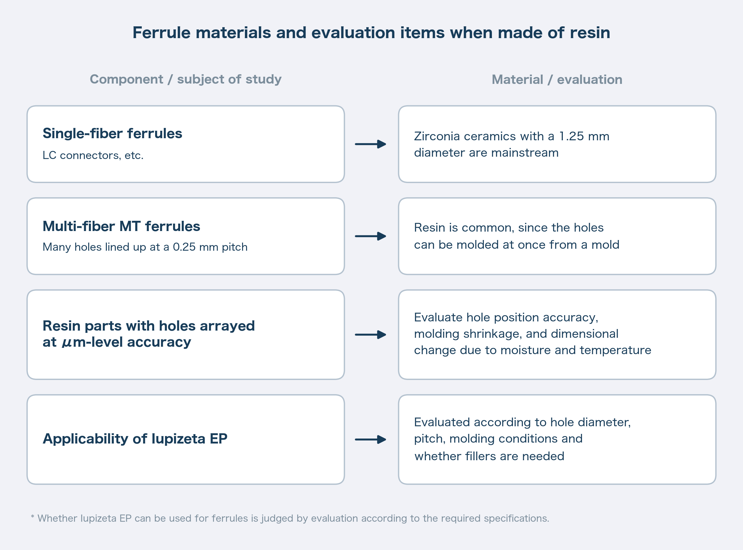
Single-fiber ferrules, such as those for LC connectors, are mainly made of zirconia ceramics with a diameter of 1.25 mm. Multi-fiber MT ferrules, on the other hand, are generally made of resin, which allows the many holes arranged at 0.25 mm intervals to be molded at once from a mold.
Scope of evaluation for Iupizeta EP
Iupizeta EP is a special optical polycarbonate resin developed by Mitsubishi Gas Chemical, with grades having refractive index nd 1.616–1.671, and it is used in parts that transmit light, such as lenses.
In parts such as MT ferrules, which arrange holes holding 125 μm-diameter fibers with μm-level accuracy, the evaluation items are hole position accuracy, molding shrinkage, and dimensional change due to moisture absorption and temperature. The applicability of Iupizeta EP requires evaluation according to hole diameter, pitch, molding conditions, and whether fillers are needed.
Housings around optical transceivers and microlens array holders are introduced, together with ultra-high-heat-resistance development materials compatible with the reflow process, in “Can optical transceiver components be made from resin? The barrier posed by glass and ceramics”.
Summary
An MT ferrule is a part that arranges and holds multiple optical fibers, and an MPO connector is a connector that houses it in a housing. MPO connectors are specified in JIS C 5982, covering 2–12 fibers in one row and 16–24 fibers in two rows, and there is also a standard for 16-fiber versions. MTP is a product name of a specific manufacturer that conforms to the MPO standards.
The more fibers there are, the harder it becomes to achieve the positional accuracy required of every hole. Single-mode ferrules need molding accuracy and dimensional stability that keep core axial misalignment below 1 μm.
For consultation on selecting resin materials for optical components or on property data, please reach out through the link below.
Some images and text in this article were created with the help of generative AI.


Recommended articles